Liquid Cooling: Infrastructure
The building and necessary modifications
To convert an air-cooled data center to liquid cooling, several factors need to be considered in order to correctly install components such as CDUs, cold plates, tanks, and pipes. Racks and servers cannot be used without modifications, even if direct-to-chip liquid cooling is used. A manifold for the pipes to the individual servers must be incorporated in the rack, and it may be necessary to insert additional holes in the rack for the pipes to exit. It’s a similar situation with the servers: here too, there must be apertures for pipes, and as these are relatively thick and cold plates need to be integrated in the housing as well, there may be a lack of space, necessitating further modifications.
The next key factor involves the more stringent safety requirements that apply when routing the pipes for the individual liquid cooling circuits – if these run on a water/glycol mixture. The pipes must be positioned so that they are not routed above active components or servers, to prevent any damage due to water ingress in the event of leakage. These pipes should ideally be laid in the raised floor, which is mostly already in place in air-cooled plants. Moreover, pipes must be regularly checked for corrosion and leaks. Pipes carrying dielectric fluids, on the other hand, tend to be unproblematic, because they are not conductive and cannot cause damage to components if they leak.

The structure of the building must also be considered when converting to liquid cooling. Generally speaking, no action needs to be taken with direct-to-chip liquid cooling, because the weight per square meter does not change significantly compared with air cooling. However, if immersion cooling is used, in larger plants there is a risk of dramatically increased point load on the ceiling due to the higher server density and large quantities of fluid. Therefore, it’s essential that structural engineers check potential ceiling loads before the conversion and that any necessary structural measures to increase load bearing capacity are taken. If, in addition, robotic arms are to be used to maintain the immersed servers, this obviously needs to be taken into account during planning, to ensure that robot systems can be mounted safely and securely and have sufficient freedom of movement.
If the cost of a complete conversion is too high, it is of course possible to convert just part of the data center surface area to liquid cooling. In some cases, perhaps it even makes more sense to construct a new building or extension, which meets the requirements for liquid cooling right from the start.
Existing air conditioning cabinets for room cooling can continue to be used for cooling residual heat that is still emitted into the room by non liquid-cooled components, such as power supply units, for example. With direct-to-chip liquid cooling, the residual heat is about 20 percent of the total heat load, while for immersion cooling it is only about 5 percent.
Coolant distribution unit (CDU) – a key component
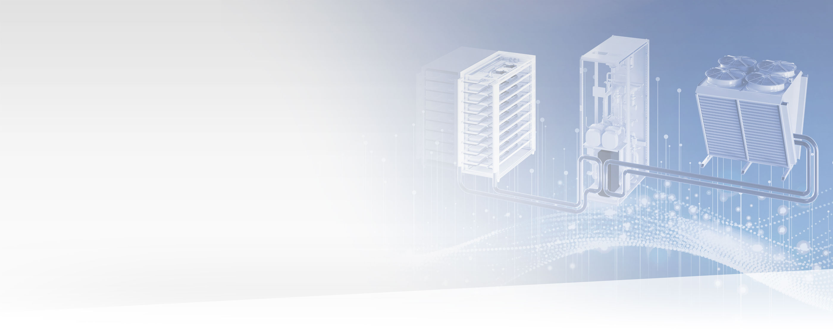
The basic design of a liquid cooling system in a data center is as follows: with direct-to-chip liquid cooling, the cold plates on the server boards are connected via flexible lines to a manifold in the rack. This rack manifold is in turn connected via pipes to a coolant distribution unit (CDU). If immersion cooling is used instead of the direct-to-chip method, the tank, not the rack, is connected to the CDU. The CDU separates the facility water system (FWS – the building’s cooling circuit) from the technology cooling system (TCS – the liquid cooling system for the servers) via a heat exchanger. In addition, the CDU uses valves and pumps to control the flow and temperature of the cooling liquid.
It’s important to separate the circuits, because different purity requirements apply to the cooling circuit and to the facility water. Moreover, dielectric fluids may also be used in the cooling circuit, not just water/glycol mixtures. The necessary liquid quality in a cooling circuit of this kind depends, among other things, on what materials the heat exchangers and cold plates are made of, and how large the integrated microchannels are. If the microchannels are very small, the maximum particle size in the liquid is a decisive factor for the reliable operation of a liquid cooling system.

What are the standards and specifications for liquid cooling?
Most data center standards do not currently include specifications or recommendations for designing suitable systems for liquid cooling. The sole exception at present is ASHRAE Guideline TC 9.9, which deals explicitly with liquid cooling. It names two recommended designs, which differ in the location and number of CDUs. The first version has a central CDU to which several racks can be connected. This saves space in the rack but occupies additional space in the server room. If this central CDU design is used, 2N redundancy should ideally be established, to compensate for failures at any time. Furthermore, the CDU capacity should be such that they offer a reserve for scaling, but are also energy efficient even at low load.

In the second version, a dedicated CDU is incorporated in each rack. This means that the racks cannot accommodate as many servers, but no additional space is needed outside the racks. If a CDU fails, this only affects a single rack; all other servers can continue to function unimpaired. Scaling is also easier to achieve, because each time another rack is added, a suitable CDU adapted to the required cooling capacity is added as well. However, with this method the system gains more heat exchangers overall, which slightly reduces the amount of cold that can be extracted from the facility water due to higher transfer losses than in versions with central CDU.

How else can liquid cooling be implemented?
Some plants do without a CDU completely. This is only possible with immersion cooling, however, because a heat exchanger to separate the circuits is already in place on the tank. The temperature needs to be regulated via the facility water, offering less flexibility than when a CDU is used. A design without CDU also has advantages, however: higher efficiency, for example, because no heat exchangers need to be used to link to the facility water, and therefore no transfer losses are produced at this point. Furthermore, no additional space is needed for housing CDUs. With direct-to-chip liquid cooling, on the other hand, a CDU is always needed. This is because the cold plate pipes have a small diameter and therefore high water quality is required for keeping the circuits clean. As a rule, the advantages mentioned at the start of this article – and the greater flexibility of the CDU version – outweigh the merits of the non-CDU version – and are the most popular choice for data centers with liquid cooling. This is also because, without system separation by a CDU, glycol has to be added to the facility water, which lowers efficiency.
As well as the two versions described above, there is another method for the use of liquid cooling. Here too, cold plates are mounted on the server boards and pipes are routed out of the housing and connected to a CDU via a manifold. Additionally, there is a so-called active rear door at the back of the rack, which can also be connected to a CDU. This contains an air-to-water heat exchanger, which transfers the residual heat from non liquid-cooled components in the rack out of the air and into the cooling circuit.

How is the facility water cooled?
All liquid cooling technologies are designed to set the temperature of the facility water in such a way that sufficient reserves are available for the cooling circuits. To prevent condensation, however, these temperature windows must not get too close to the dew point of the room. In all liquid cooling versions, the facility water is cooled in a similar way to air cooling, but generally at higher temperatures. And depending on the required temperature, dry coolers, cooling towers, and chillers may be used. As guidance, ASHRAE TC 9.9 has defined temperature classes with recommendations on what kind of cooling can be used for what temperature of facility water. If the data center was already equipped with Free or Indirect Free Cooling for the facility water before the conversion, this may – depending on the required temperature level – be used to supply the CDU.
Now that we have had an in-depth look at the necessary infrastructure for liquid cooling in a data center in this article, in the next part we will examine how this kind of solution can be implemented in practice using products from Stulz, and what special factors there are to consider.